New Method for Evaluating Electrode Uniformity
In recent years, the new energy industry has increasingly demanded higher energy density and power performance of batteries. Higher energy density batteries and more powerful lithium-ion battery technologies are in urgent need of development. Lithium-ion battery resistance is one of the important indicators for measuring battery performance. The size of the battery resistance directly affects the capacity, power, cycle life and safety performance of the lithium-ion battery [1-2]. Factors that affect the resistance of lithium-ion batteries include electrode materials, formulas, electrolytes, homogenization coating processes, electrode resistance, etc. Among them, electrode resistance reflects the performance of electrode materials and the quality of the formula.
In porous electrodes, solid-phase conductive particles form an electronic conductive network, which is distributed in the liquid-phase ion transport network composed of pore electrolyte. Therefore, the structural design of the electronic conductive network and ion transport network in porous electrodes is closely related to the electrode performance. How to assemble active materials, conductive agents and binders into composite electrodes that conduct ions and electrons efficiently is of great significance to improving battery performance. At the same time, because the tortuosity of the electrode (McMullin number) represents the degree of curvature of the porous electrode transmission path, it can characterize the difficulty of lithium-ion migration in the coating. The relationship with the parameters related to the porous electrode transmission characteristics can be expressed by the formula (1) to represent [3]:

In the formula: Deff represents the effective diffusion rate; D0 represents the intrinsic diffusivity of the material itself; ε is the porosity in the porous electrode; τ is the tortuosity of the electrode, and Nm is the McMullin number. The effective ionic conductivity can be found to be inversely proportional to the tortuosity of the electrode. Therefore, to improve the permeability of the electrolyte and the migration rate of ions, the design of electrode structures with low tortuosity has become a key principle in porous electrode design [4].
This article mainly uses the same deposition process and coating process to continuously produce four batches of vapor-phase silicon carbon negative electrode, and uses IEST's battery electrode resistance analyzer (BER2500, IEST) to evaluate the electronic conductive performance of the finished electrode, a multi-channel ion conductivity test system (EIC1400K, IEST) was used to evaluate the ion conductivity performance of the finished electrode. By testing the resistance of the electrode, the stability of the electrode batches is evaluated.
1. Test Conditions & Methods
1.1 Test Equipment
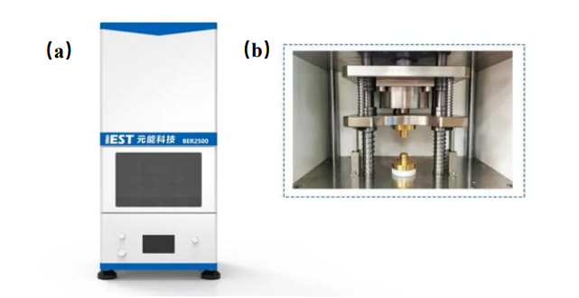
Figure 1. Electrode Resistance Analyzer (BER2500) appearance (a) and internal structure diagram (b)
Electrode electronic resistance test: Figure 1 shows the electrode resistance analyzer (BER2500, IEST) independently developed by IEST. The diameter of the electrode sample is 14mm, and the applied pressure range is 5~60MPa. Parameters such as resistance, resistivity, conductivity, compaction density of the electrode can be collected simultaneously. The equipment is shown in Figure 1 (a) and (b).
Electrode ion resistance test: The multi-channel ion conductivity test system (EIC1400K, IEST) developed by IEST is used as shown in Figure 2. The equipment contains 4 symmetrical battery assembly fixture (Figure 2 (b)), four-channel rapid electrochemical impedance spectroscopy testing can be achieved. Pressure range 0~20Kg, frequency range 1500~0.1Hz.
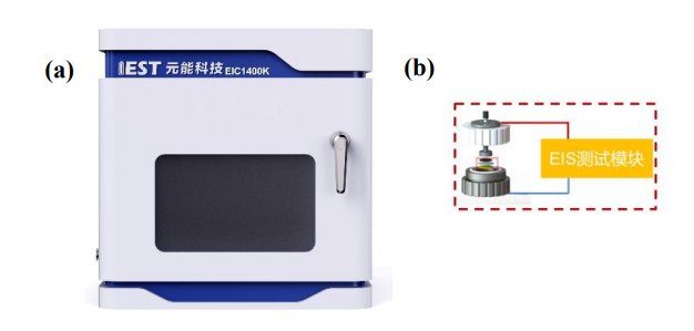
Figure 2. Multi-channel ion conductivity testing system: Equipment appearance (a); Battery assembly fixture (b)
1.2 Test Samples
Using the same deposition process and slurry coating process, four consecutive batches of gas-phase silicon-carbon negative electrode (B1, B2, B3, B4) were produced; The slurry formula is: gas-phase silicon-carbon: SP: CNT: LA133 = 94%: 1%: 1%: 4%.
1.3 Test Procedure
Electrode electron resistance testing: Prepare one sheet each from four batches of 5*10cm electrode. Set up testing parameters in MRMS software, select single-point testing mode, with a pressure of 5MPa and holding pressure for 15 seconds. Sample 6 data points from each electrode. The software automatically reads data such as electrode thickness, resistance, resistivity, conductivity, etc.
Electrode ion resistance testing: Assemble symmetric cells with electrode using fixtures inside the glovebox. Place the assembled fixtures into the equipment and apply a pressure of 20kg to the fixtures. After approximately 10 minutes, initiate the experiment on the software interface, test battery electrochemical impedance, finally, obtain the MacMullin number of the electrode through fitting and calculation using the software.
1.4 MacMullin Number Calculation Method

In the equation, τ represents tortuosity; Rion stands for ion resistance; A denotes the electrode area; ε signifies the electrode porosity; σ represents the electrolyte conductivity; and d stands for the thickness of the electrode. Due to the complexity of testing electrode porosity, it is commonly represented by the ratio of tortuosity to porosity, known as the MacMullin number (Nm = τ / ε), to characterize the tortuosity of the electrode, as shown in equation (3).

Using the electrochemical workstation to test the electrochemical impedance spectrum of symmetrical cells, as shown in Figure 3. At this point, the Nyquist plot of the electrochemical impedance spectrum exhibits the characteristic shape of intersecting line segments in the low-frequency and high-frequency regions, which is typical of Nyquist plots without electrochemical reactions. Extend the low-frequency line segment of the Nyquist plot until it intersects the X-axis; the value of the abscissa at this point is Rh. The value of the intersection of the high-frequency line segment and the X-axis is Re. The ionic impedance of the coating, Rion= (Rh-Re) *3. Substituting the fitted ionic impedance Rion into equation (3) yields the MacMullin number of the electrode, thereby analyzing the tortuosity of the electrode.
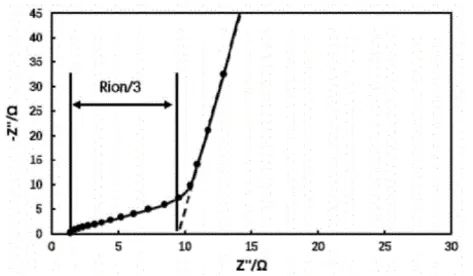
Figure 3. Electrochemical impedance spectrum of symmetrical cell
2. Result Analysis
2.1 Analysis of Electrode Electron Resistance

Figure 4. Test Results of Resistance (a) and Resistivity (b) for Electrodes from Different Batches
From the trends in electrode resistance and resistivity shown in Figure 4, it can be observed that the consistency of electrode resistance for Batch 1 is poor, while Batches 2, 3, and 4 exhibit better consistency, with a coefficient of variation (COV) < 5%. However, there are still differences in electrode resistance among batches. This indicates that although the preparation process is consistent and the same conductive additives are added, the conductivity and morphology of the active material itself can also affect the electrode's electrical performance, thus influencing battery performance.
2.2 Analysis of Electrode Ion Resistance
Different batches of silicon-carbon negative electrode sheets were assembled into symmetrical cells for electrochemical impedance spectroscopy testing, as shown in Figures 5(a), 5(b), 5(c), and 5(d). The impedance spectra were fitted to obtain the ion resistance of each batch of electrode. Then, the ion resistance values were substituted into Equation (3) to obtain the MacMullin numbers of the electrode, as shown in Table 1. From the values of ion resistance (Rion) and MacMullin numbers (Nm), it can be observed that the trends are similar to those of electron resistance. Batch 1 exhibits poor consistency in ion resistance, while the other three batches show better consistency. However, there are still some differences in ion resistance.
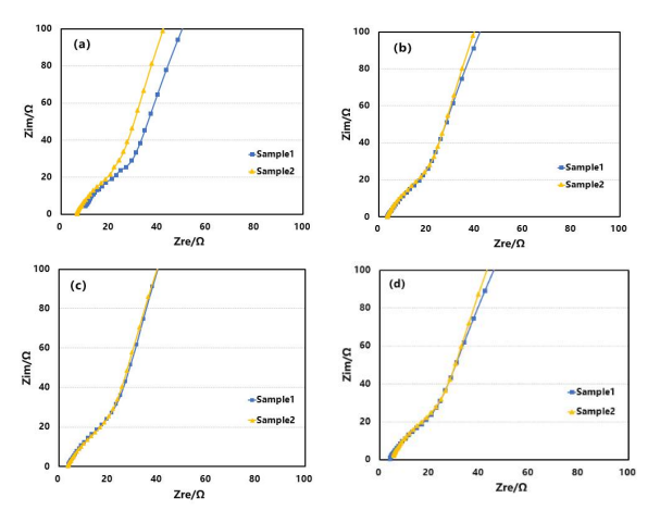
Figure 5. Impedance Spectra of Electrode from Different Batches: B1(a); B2(b); B3(c); and B4(d)
Table 1. Ion Resistance and MacMullin Number of Silicon-Carbon Negative Electrodes from Different Batches
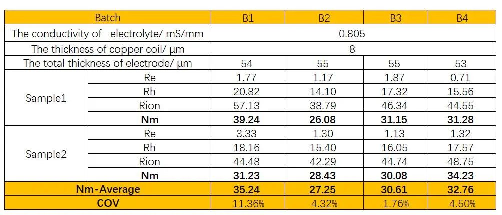
Based on the above analysis, it can be observed that the trends of electron resistance and ion resistance of silicon-carbon negative electrode from different batches are quite consistent. Testing the electrode resistance can help identify samples with poor consistency at the electrode end, enabling rapid identification of batch anomalies, which is important for improving production efficiency and product quality.
3. Conclusion
In this study, the electrode electron resistance and ion resistance of four consecutive batches of gas-phase silicon electrodes produced using the same process were tested using the electrode resistance analyzer (BER2500, IEST) and multi-channel ion conductivity testing system (EIC1400K, IEST) developed by IEST. The results indicate that the trends of electrode electron resistance and ion resistance are consistent, and both can detect anomalous electrodes. The difference in electron conductivity reflects the uniformity of the conductive agent network, indicating uneven dispersion of the conductive agent in Batch 1 electrodes during preparation. Since the conductive agent is typically dispersed within the pores of active particles, uneven dispersion of pores in the electrodes can be inferred. Lithium ions conduct through the electrolyte within the pores, and the conductivity characteristics are closely related to porosity. Non-uniform dispersion of pores leads to poor consistency in electrode ion resistance.
During the production process of electrode, anomalies in batches can be identified by monitoring both electron resistance and ion resistance of the electrode. This provides a rapid detection method for research and monitoring the stability of production line batches. Researchers can also preliminarily assess the electrochemical performance of electrode assembled into batteries by testing their ion resistance and MacMullin number, thereby shortening the material evaluation cycle and improving research and development efficiency.
4. References
[1] 魏学哲,徐玮,沈丹. 锂离子电池电阻辨识及其在寿命估计中的应用[J]. 电源技术,2009, 33(3):217-220.
[2] 徐晓东,刘洪文. 锂离子电池电阻测试方法研究[J]. 中国测试, 2010,36(6):24-26.
[3] Kuang Y, Chaoji C, Kirsch D, et al. Thick Electrode Batteries: Principles, Opportunities, and Challenges [J]. Advanced Energy Materials, 2019, 9 (33) : 1-19.
[4].Waldmann T, Hogg B I, Wohlfahrt-Mehrens M. Li plating as unwanted side reaction in commercial Li-ion cells-A review. Journal of Power Sources, 2018, 384: 107-124.

