Stability Monitoring Plan for Gas-Phase Silicon Carbide Negative Electrode Production Batches
With the booming development of the new energy industry, lithium-ion batteries are gradually developing toward higher energy density and longer cycle life. The existing graphite anode has a theoretical gram capacity of only 372mAh/g, which is no longer able to meet future demands for battery energy density. Silicon-based anodes have gradually become the next-generation lithium battery anode material that can replace graphite because of their high theoretical gram capacity, which is nearly ten times that of graphite. They also have the advantages of rich content and high lithium insertion potential.
However, in actual applications, silicon will produce a huge volume expansion (~300%) when alloying with lithium, this volume change will induce the accumulation of internal stress in the electrode, leading to the powdering of active particles, destruction of the electrode structure, and rapid capacity attenuation. At the same time, the SEI film on the surface of the silicon negative electrode will rupture as the silicon volume changes, causing the SEI film to rupture and regenerate cyclically during subsequent charge and discharge processes, resulting in greater loss of active lithium and thus reducing service life. Moreover, there are also problems such as low first Coulombic efficiency and poor electrical conductivity compared with carbon materials, which limit the practical application of silicon anode materials [1]. Therefore, research on silicon anodes in recent years has mainly focused on using silicon oxidation, nanonization, composite, porous, alloying, prelithiation, premagnesization and other modification methods to alleviate the problems faced by silicon-based anode materials[2].
There are two major categories of silicon-based materials that have been commercialized: silicon-oxygenated carbon composites (silicon-oxygen) and silicon-carbon composites (silicon-carbon). The technical routes are mainly the grinding nano-silicon-carbon route and the silicon-oxygen route. However, there are some problems in both technical routes: (1) The size of silicon particles ground by silicon carbon grinding method [3] is about 100nm, and there are problems such as particle agglomeration and certain expansion, the biggest shortcoming is cycle performance, which is difficult to meet the needs of practical applications. Nano-silicon usually needs to be coated and modified. At present, the mainstream use of "carbon-coated silicon" material structure similar to a fruit shell to reduce the risk of crushing, different raw material addition proportions have an impact on the material's Coulombic efficiency, rate performance, and cycle performance. (2) Silica carbon composite materials (silicon-oxygen) [4] have lower theoretical specific capacities than Si materials, but their volume expansion during the lithium insertion process is greatly reduced (about 118%), its cycle performance is greatly improved. However, because the silicon oxide anode produces inactive substances such as Li2O during the charge and discharge process, the SiOx material has a large irreversible capacity loss and a low first efficiency (about 70%). Therefore, the first efficiency, specific capacity, and cycle life of silicone oxide carbon anodes can be improved through carbon coating, pre-lithium, pre-magnesium, and metal doping. Among them, the first efficiency of pre-lithiated silicon-oxygen anode can be increased to 86%~90%, but this inevitably brings about the problem of high cost. The current commercial application capacity of silicon-oxygen anode is mainly 450 to 500mAh/g. The cost is high and the first effect is relatively low. However, the cycle performance is relatively good, and it is mainly used in the field of power batteries.
At present, it is necessary to further improve the performance of silicon-based anode materials, so a new generation of technology - vapor deposition silicon carbon technology using CVD method [5] emerged at the historic moment, it soon started a craze and became the “new favorite” in today’s lithium battery anode material market. However, there are also difficulties in the industrialization process of vapor deposition silicon carbon, which mainly lie in three main aspects: porous carbon selection, deposition equipment and deposition process:
(1) The quality of the carbon skeleton directly determines the mass production capacity of future products. Different porous carbons need to be matched with different graphites to show good performance at the battery end.
(2) Because the rotary kiln is prone to poor performance due to uneven silicon deposition and incomplete carbon coating during the production process. At the same time, the silane utilization rate of the rotary kiln is low, and it will also lose a certain competitiveness in mass production due to higher costs. Although the fluidized bed has more uniform deposition and higher silane utilization, it requires equipment with high airtightness and high air pressure to meet the gaseous coating of small particles, which faces difficulties in achieving mass production scale-up.
(3) The relative barriers of the deposition process in small trials are relatively small, but the consistency requirements of the mass production process are extremely high, including hundreds of kilograms of mixed material, furnace cavity temperature zones, and cavity partial pressures, the residence time of deposition in the cavity needs to be further explored.
This article mainly combines the use of the same carbon skeleton and the same deposition equipment to use two different deposition processes to continuously produce four batches of vaporized silicon carbon powder materials, the conductive properties of powder materials are measured and evaluated using a powder resistivity & compaction density meter (PRCD3100, IEST). Next, the powder is prepared and coated with slurry, and a pole piece resistance meter (BER2500, IEST) is used to evaluate the electronic conductivity of the finished pole piece. Finally, the pole pieces were assembled into a button battery, and the correlation between its powder, pole pieces and electrical properties was preliminary explored.
1. Test Conditions
1.1 Test Equipment:
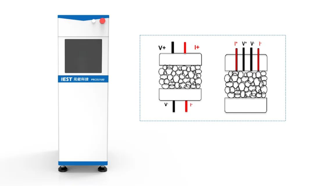
Figure 1 shows the powder resistivity & compaction density meter (PRCD3100) independently developed by IEST. The device can apply different pressures (up to 5T) to powder samples while simultaneously collect the resistivity, conductivity, compaction density and other parameters of powder samples to assist researchers in studying the effects of different pressures on the electrical and mechanical properties of powder samples.
Figure 1. Schematic diagram of the powder resistivity & compaction density meter (PRCD3100, IEST) and the two testing principles of powder resistivity
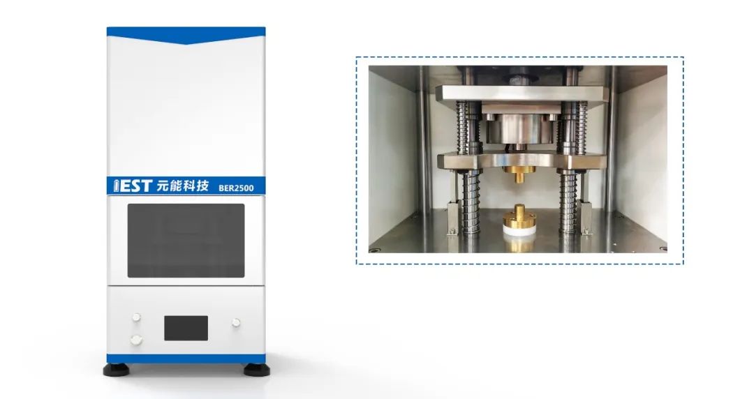
Figure 2 shows the pole piece resistance meter (BER2500) independently developed by IEST. The diameter of the electrode sample is 14mm, and the applied pressure range is 5~60MPa. Parameters such as resistance, resistivity, conductivity, compaction density, etc. of the pole pieces can be collected simultaneously. The equipment is shown in Figures 2(a) and 2(b).
Figure 2 (a) BER2500 appearance; (b) BER2500 structure diagram
1.2 Experimental Process:
(1) Powder Resistance Test
① Prepare 2 groups of silicon carbon materials with different production processes. Each group has 4 production batches, namely GA-1, GA-2, GA-3, GA-4 and GB-1, GB-2, and GB-3, GB-4.
② Within the pressure range of 6~20MPa, use 2MPa as a step interval and maintain the pressure for 10s; within the pressure range of 20MPa-100MPa, step by 20MPa and maintain the pressure for 10s; Within the pressure range of 100MPa-200MPa, step by 50MPa and hold the pressure for 10s; step by step to apply pressure on the above two sets of silicon carbon anodes, and use the four-probe resistance test module and thickness test module that come with PRCD3100, record the resistivity and thickness changes under different pressures in real time to obtain the changes in resistivity & compaction density of these two groups of silicon carbon anodes with pressure;
(2) Electrode Resistance Test
① Prepare the single-sided pole pieces prepared from the above two sets of silicon carbon powders, namely JA-1, JA-2, JA-3, JA-4 and JB-1, JB-2, JB-3, JB-4 .
②Set the test parameters on the MRMS software, select the single-point test mode, select the pressure of 5MPa, hold the pressure for 15s, sample 6 data for each pole piece, and the software automatically reads the pole piece thickness, resistance, resistivity, conductivity and other data.
Table 1 Slurry Mixing Formula
2.Data Analysis
2.1 Powder Resistance Analysis:
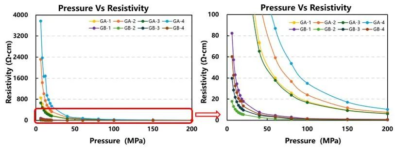
Figure 3. Powder resistivity test results
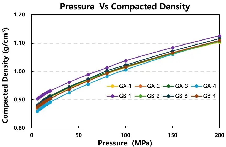
Figure 4. Powder compaction density test results
Figures 3 and 4 show the resistivity and compaction density change curves of 2 sets of 4 production batches of silicon-carbon anode materials with different preparation processes as pressure changes. As can be seen from Figure 3, the resistivity of silicon-carbon anode materials gradually decreases as the pressure increases, indicating that large pressure helps reduce the contact resistance between powder materials, thereby improving the electron transport capability of the material. The resistivity of GA is significantly greater than the resistivity of GB, indicating that the conductivity of the silicon carbon anode prepared by process B is better than that of the silicon carbon anode prepared by process A. Comparing the resistivity of different batches of silicon-carbon anodes under different pressures using the same preparation process, the changing trend is the same, but the difference is larger under small pressures, and the consistency between different batches is poor, on the one hand, this shows that the current fluidized bed deposition process is not stable enough. On the other hand, due to the complex contact state between powders, the error in the low pressure test results is larger. After the pressure is greater than 100MPa, the resistivities between different batches of GB are close, while the resistivities of different batches of GA are still significantly different. The uniformity of silicon particles deposited by preparation process B is higher than that of preparation process A.
From the changing trend of compacted density with pressure in Figure 4, it can be seen that the changing trends of compacted density of silicon carbon anodes produced by these two preparation processes are consistent, and the difference between the two is relatively small. However, the compaction density of preparation process A is slightly lower than the compaction density of preparation process B, this shows that the silicon carbon prepared by preparation process A is relatively loose and can embed more silicon. Due to the poor conductivity of silicon, the resistance of GA will be higher than that of GB.
2.2 Electrode Resistance Analysis:
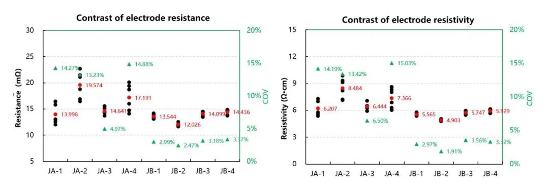
Figure 5: Electrode Resistance and Resistivity Test Results
From the trend of pole piece resistance and resistivity in Figure 5, it can be seen that the resistance and resistivity of JA pole pieces prepared using GA are greater than the resistance and resistivity of JB pole pieces prepared using GB, although the same conductive agent is added during the preparation process of the pole piece, the conductivity and morphology of the active material itself will also affect the conductivity of the pole piece, thereby ultimately affecting the battery performance. Moreover, the COV values of JA’s pole piece resistance and resistivity are larger than those of JB, which is the same trend as that of powder, from the batch consistency of powder resistivity in Figure 3, the silicon carbon powder in the GA group has poor uniformity, it is not easy to disperse evenly during the preparation process of the slurry. After the slurry is prepared into pole pieces, the consistency of the pole piece resistance is even worse (Figure 5).
2.3 Discharge Data Analysis:
Table 2: Discharge Electrochemical Performance Test Results
The above-mentioned pole pieces were prepared into buckles and electrical performance tests were conducted. As can be seen from Table 2, in general, the charging capacity of group JA is greater than that of group JB, the possible reason is that during the deposition process of silicon carbon, the silicon content of GA is higher than that of GB, so the charging capacity of group JA is higher than that of group JB. The withholding data of JA-4 is abnormal compared with the other three batches. When extrapolated to the powder, the resistance of GA-4 is also abnormally high (Figure 3) and the compaction density is low (Figure 4); Similarly, the charging gram capacity of JB-2 is low, and inferring the powder, the resistance of GB-2 is low (Figure 3), which may be caused by the low silicon content.
It can be seen from the above analysis that the resistivity and compaction density of silicon carbon powders of different processes and batches have a relatively good correlation with the final battery performance. This correlation makes the detection of parameters such as resistivity and compaction density of active particle powder an effective means of predicting final battery performance. By accumulating a certain amount of powder characterization test data during production, we can establish this correlation, allowing us to quickly identify batch anomalies and predict final cell performance. Therefore, the detection of parameters such as resistivity and compacted density of active granular powder is of great significance for improving production efficiency and product quality.
3. Conclusion
This paper uses the powder resistivity & compaction density meter (PRCD3100) and pole piece resistance meter (BER2500) developed by IEST use four batches of vaporized silicon carbon powder materials were continuously produced by two different deposition processes to conduct resistivity and compaction density tests under different pressures and pole piece resistance tests and explore the differences between powder resistance and pole piece resistance between batches of different processes. From the powder resistance and compaction density data, it can be seen that the conductivity and compaction density of the silicon carbon negative electrode prepared by process B are better than those of the silicon carbon negative electrode prepared by process A and the batch consistency of process B is also better than that of process A, which is the same trend as the pole piece; the abnormal batch at the powder end also reflects abnormal data in the electrical performance of the power deduction. Therefore, in the production process of gas phase silicon carbon, abnormal batches or production processes can be quickly screened out by monitoring the powder resistivity, compaction density and resistance of the pole pieces, it provides a rapid detection method for R&D and production line batch stability monitoring, thereby safeguarding lithium-ion battery R&D and production.
References
[1]Q. Liu, Y. Hu, X. Yu, et al. The Pursuit of Commercial Silicon-Based Microparticle Anodes for Advanced Lithium-Ion Batteries: A Review. Nano Research Energy. 2022, 1: e9120037.
[2] Hu B, Jiang S, Shkrob I A, Zhang J, Trask S E, Polzin B J, et al. Understanding of prelithiation of poly(acrylic acid) binder: Striking the balances between the cyclingperformance and slurry stability for silicon-graphite composite electrodes in Li-ionbatteries[J].Journal of Power Sources.2019,416(1):125-131.
[3]WANG W,KUMTA P N.Nanostructured hybrid silicon/carbon nanotube heterostructures:reversible high-capacity lithium-ion anodes[J].ACS Nano,2010,4(4):2233-2241.
[4]Shi H,Zhang H,Li X,et al.In situ fabrication of dual coating structured SiO composite as high-performance lithium-ion battery anode by fluidized bed chemical vapor deposition[J]. Carbon,2020,168:113-124
[5]CABELLO M,GUCCIARDI E,HERRÁN A,et al.Towards a high-power Si@graphite anode for lithium ion batteries through a wet ball milling process[J].Molecules,2020,25(11):2494.

