Literature Review: Design of PDMS Capsules for Modifying Cobalt-Free Nickel-Rich Layered Cathode Materials

Literature Review: Design of PDMS Capsules for Modifying Cobalt-Free Nickel-Rich Layered Cathode Materials
1. Article Abstract
Nickel-rich layered oxides are among the promising materials for the next generation of high-energy-density lithium-ion batteries. Although increasing nickel content can enhance the battery's specific capacity, it also increases the sensitivity of the cathode to environmental degradation and internal electrolyte side reactions. These factors worsen the material's electrochemical performance, storage stability, and thermal stability. Inspired by the "slow-release capsule" mechanism, the authors of this paper use polydimethylsiloxane (PDMS), a material known for its excellent moisture resistance and chemical stability, as a coating modifier on the surface of cobalt-free nickel-rich LiNi0.9Mn0.1O2 cathode.
The hydrophobic properties of PDMS enhance the stability of environmental air storage by disrupting the interaction between the cathode and water molecules. During electrochemical cycling, PDMS exhibits another functional mechanism to address chemical responses: trace amounts of moisture induce the decomposition of electrolytes, producing harmful HF substances that can be effectively captured and eliminated, thereby suppressing cathode corrosion and enhancing interface stability during long-term cycling.
Thanks to seamless protection from the external to internal aspects of the battery, this well-encapsulated nickel-rich cathode exhibits minimal capacity decay even after prolonged exposure to the environment. Moreover, it endows the nickel-rich material with superior cycling performance and thermal stability during cycling. This work provides a new perspective on cathode modification from the standpoint of designing intelligent responsive coatings to suppress its sensitivity to the surrounding environment. Figure 1 illustrates the schematic diagram of the "Cathode@PDMS" capsule design.
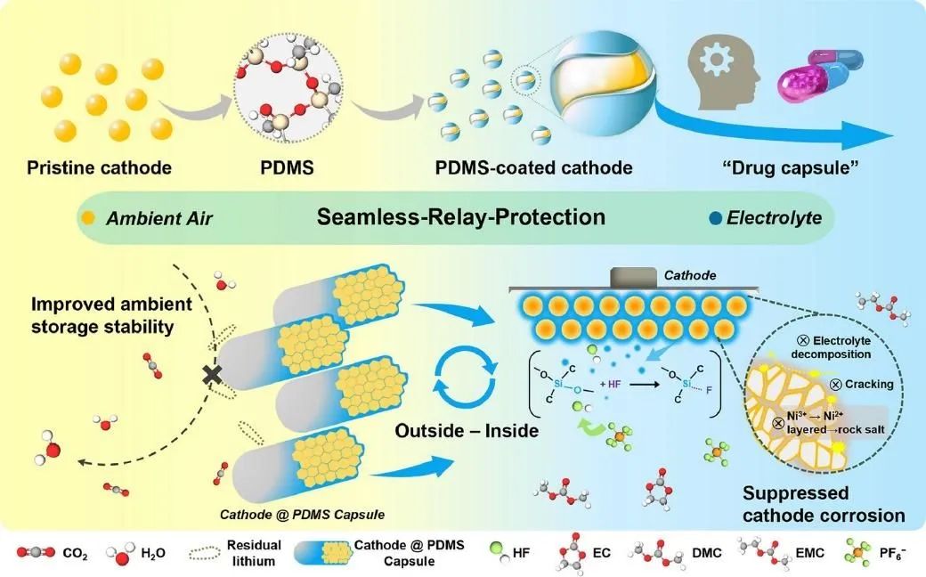
Figure 1: Schematic Diagram of "Cathode@PDMS" Capsule Design with Intelligent Responsive Protection from Outer to Inner Layers.
2. Analysis of Figures and Text
The research subject of this article employs cobalt-free nickel-rich LiNi0.9Mn0.1O2 material, with PDMS deposited on the particle surface using a wet chemistry process, resulting in a PDMS-modified capsule-like structure.
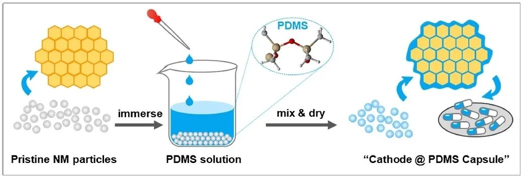
Figure 2. Schematic Diagram of the Synthesis Method for PDMS-Coated Modified Cathode Material.
In terms of material characterization, standardized X-ray diffraction (XRD) was employed for the analysis of material crystal structure. Scanning electron microscopy (SEM) and high-resolution transmission electron microscopy (HRTEM) were utilized for observing the micro/nano-level morphology and lattice structure of the materials. Inductively coupled plasma optical emission spectrometry (ICP-OES) was used to determine the content of relevant elements. Fourier-transform infrared spectroscopy (FTIR) was employed for functional group analysis.
Atomic force microscopy was used for surface potential mapping, while automatic potential titration equipment was utilized for detecting residual lithium content, aiming to evaluate the performance differences before and after material modification. Furthermore, non-standard testing techniques, such as powder resistivity & compacted density meter (PRCD series, IEST) for powder conductivity testing and bipolar electrode resistivity meter (BER series, IEST) for electrode resistivity, thickness, and deformation testing, were combined to further clarify the differences in physicochemical indicators of the materials before and after modification, as well as the subsequent electrode layer hierarchy.
Figure 3(a) presents the SEM comparison between the pristine material (NM) and the modified material with PDMS coating (S-NM). Both samples exhibit spherical polycrystalline morphology with uniform sizes distributed in the range of 4-5 μm. Under SEM observation, the surface of particles after PDMS coating appears as a continuous, smooth gel-like layer.
The comparative results of FTIR spectra in Figure 3(b) show that compared to the peaks of pure PDMS, the peaks of PDMS in the coated samples appear broader with slight frequency shifts, indicating the presence of chemical interactions between the lattice lithium and PDMS, which facilitates the conduction of lithium ions. XRD results in Figure 3(c) indicate no significant changes in the crystal structure between NM and S-NM. Additionally, combined with the HRTEM images in Figure 3(d) and FFT mode, the presence of amorphous PDMS on the surface is observed, further confirming that there are no significant changes in the crystal phase structure before and after material coating. The morphology and structural performance of the materials preliminarily verify that this process can successfully achieve material modification without disrupting the layered structure.
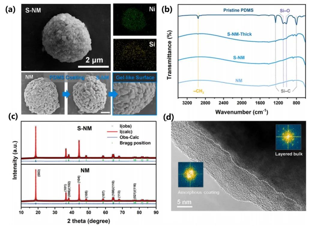
Figure 3. (a) SEM images and EDS results of NM and S-NM, with a scale bar length of 2 μm; (b) FTIR spectra of NM and S-NM; (c) XRD spectra of NM and S-NM; (d) HRTEM images combined with FFT mode analysis.
Figure 4 shows the contact angle test, total residual lithium compound content test, powder resistivity test, SEM morphology test, and storage stability test in PVDF solution for the materials. From the test results, it is evident that the S-NM material exhibits better moisture resistance and storage stability. Particularly, in Figure 4(c), the conductivity test results of NM and S-NM before and after storage indicate nearly linear growth in conductivity within the test pressure range.
Although the conductivity of fresh NM and S-NM cathodes is similar, the conductivity of stored NM powder is significantly lower than that of S-NM, further indicating the different surface state changes of the two after air exposure. The PDMS coating suppresses the accumulation of Li2CO3, an adverse conductive substance on the surface, thereby enhancing the storage stability of S-NM and effectively inhibiting the increase in internal resistance of the electrode, which is beneficial for subsequent long-term cycling stability.
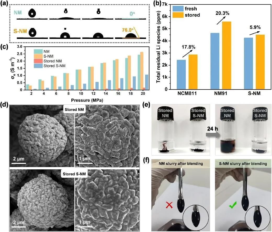
Figure 4. (a) the contact angle between the material and water before and after coating; (b) determination of residual lithium compound content on the nickel-rich cathode; (c) powder resistivity under different pressures; (d) SEM images of the materials after storage; (e) color changes of the materials stored in PVDF solution; and (f) optical images of the stirred slurry.
To further elucidate the differences in electrochemical performance before and after material modification, the structural evolution during the initial cycling process was investigated using in-situ X-ray diffraction, as shown in Figures 5(a) and (b), confirming that the continuous insertion and extraction of Li+ ions and phase transitions were not hindered by PDMS modification. Half-cells were assembled with NM and S-NM cathodes to evaluate the internal protective effect of PDMS. Figure 4(c) shows the cyclic voltammetry results, where good overlap of peaks indicates that the electrochemical properties of the material remain unchanged after PDMS coating.
Over the three cycles, the narrower gap between oxidation-reduction peaks of S-NM suggests lower polarization, indicating a positive influence of the surface coating on lithium-ion dynamics. To study the mechanism of electrode polarization and cycle performance improvement, analysis was conducted using the dQ/dV curve, as shown in Figure 4(f). The peak variation around 4.2 V in the dQ/dV curve represents the H2-H3 phase transition, which is the main cause of structural collapse and microcrack propagation in the material. By comparison, the harmful H2-H3 phase transition was effectively alleviated after PDMS modification, demonstrating that the presence of the PDMS layer can delay structural degradation during cycling.
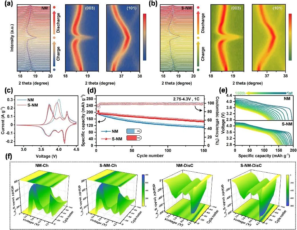
Figure 5. (a) In-situ XRD testing of the NM and (b) S-NM cathodes during the initial cycling. (c) CV curves of the NM and S-NM cathodes for the first three cycles. (d) Cycling performance at 1C rate. (e) Discharge curves during cycling at 1C rate. (f) dQ/dV curves corresponding to 100 cycles.
To further validate the enhancing effect of PDMS, the authors conducted systematic analyses focusing on the interactions between the electrode and electrolyte interface, HF removal capability, and physicochemical properties of the electrode after cycling, utilizing SEM, XRD, HRTEM, and XAS techniques. The results, as shown in Figure 6, clearly demonstrate that the PDMS coating can prevent unfavorable side reactions of the electrolyte, alleviate particle cracking, and thus help suppress capacity decay. Thermal stability is closely related to battery safety. In this study, the authors employed differential scanning calorimetry (DSC), XRD after thermal decomposition, and thermogravimetric analysis to assess the improvement in thermal stability of the materials, indicating effective enhancement of thermal stability after PDMS modification.
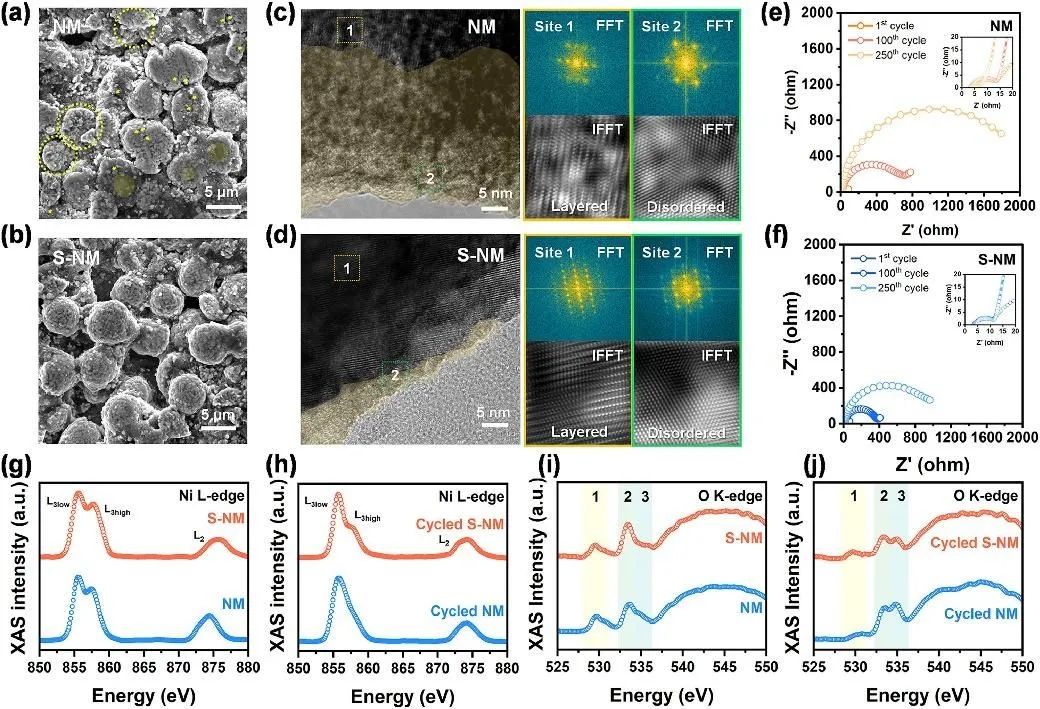
Figure 6. Post-cycling analysis of NM and S-NM cathodes: (a, b) SEM images of particles after cycling for NM and S-NM cathodes; (c, d) HRTEM images; (e, f) Nyquist plots for the 1st, 100th, and 250th cycles at 1C rate; (g-j) XAS spectra of NM and S-NM cathodes in TEY mode.
3. Summary
While nickel-rich cathodes offer high specific capacities, concerns have arisen regarding their storage, cycling, and thermal stability. Throughout the entire process, from synthesis, post-treatment, packaging, transfer, manufacturing, to eventual electrochemical cycling within batteries, the material faces challenges posed by environmental sensitivity, with trace moisture often being identified as a primary culprit. In order to systematically address the issue of material degradation involving water throughout the entire process, this study proposes a PDMS modification mechanism. The PDMS-coated material fundamentally disrupts the interaction between environmental moisture and the cathode through its excellent hydrophobicity, thereby enhancing storage stability.
Upon transitioning to internal battery cycling, the modified cathode's PDMS surface, with its silicon-oxygen groups, captures harmful HF species, enabling their immediate conversion and removal, effectively inhibiting their corrosive effects on the cathode and disrupting the degradation mechanism they induce. Thanks to this seamless protection from external to internal layers, the electrochemical performance of the modified cathode exhibits only slight degradation after prolonged exposure to air, while showing significantly improved cycling performance during normal cycling processes. Additionally, the thermal stability of the material is enhanced due to the high thermal stability of the PDMS coating and its shielding effect on lattice oxygen release.
4. Literature Original
Qi Shi, Feng Wu, Haoyu Wang , Yun Lu , Jinyang Dong , Jiayu Zhao , Yibiao Guan , Bin Zhang , Rui Tang , Yun Liu , Jinzhong Liu , Yuefeng Su*, Lai Chen*
Smart-responsive sustained-release capsule design enables superior air
Storage stability and reinforced electrochemical performance of cobalt-free
Nickel-rich layered cathodes for lithium-ion batteries. Energy Storage Materials Volume 67, March 2024, 103264
https://doi.org/10.1016/j.ensm.2024.103264
