Decomposition Method for Contact Resistance of Lithium Electrode Sheets
The pole piece is an important output of the front-end process of the battery. The electronic resistance (conductivity) of the pole piece affects the power, reliability and safety of the full battery. At the same time, it is closely related to the stirring, coating and rolling processes. Therefore, the measurement The change of pole piece resistance can better evaluate the performance of the electronically conductive network during the pole piece production process, evaluate the uniformity of the electrode microstructure and monitor the stability of the pole piece manufacturing process, and help improve the formula of the pole piece and the mixing, coating and Control parameters of the rolling process. At present, the electronic resistance of the pole piece is mainly characterized by the two-probe method to characterize the overall penetration internal resistance of the pole piece. The measured total resistance includes coating resistance, coating and current collector interface resistance, and current collector itself resistance¹⁻⁴, For example, the schematic diagram of characterizing the electronic resistance of a single-sided pole piece is shown in Figure 1, where RAM represents the electronic conductivity between the solid particles inside the electrode coating, and R2 represents the contact resistance between the coating and the current collector, which can be used to evaluate the adhesion The adhesion performance between the junction agent and the coating and the current collector, and R1 and R4 are the parasitic resistances introduced by the two-probe method, and these two parts are expected to be deducted.
In the process of pole piece electronic testing, in order to control the quality of the electrode coating more finely, we often hope that the tested resistance value can be further decomposed, and RAM, R2, R1 and R4 are calculated separately, and then the pole piece can be controlled more precisely Quality, such as optimizing the formula to improve the conductivity of the electrode coating, reducing the interface resistance between the coating and the current collector, etc. The purpose of this paper is to provide a decomposition method for testing the total resistance of the pole piece. When decomposing the contact resistance, it is first assumed that the electrode layer of the active material is a pure-phase conductor structure, and the electron conduction satisfies Ohm’s law; secondly, the parasitic resistance introduced in the test process and the interface resistance between the coating and the current collector are unified into the contact resistance, then all The electrode sheet resistance tested includes two parts: the resistance of the electrode coating itself and the contact resistance. On the basis of the above assumptions, we decompose the contact resistance by testing the electrode resistance of different thicknesses, so as to conduct a preliminary analysis of the contact resistance in different states.
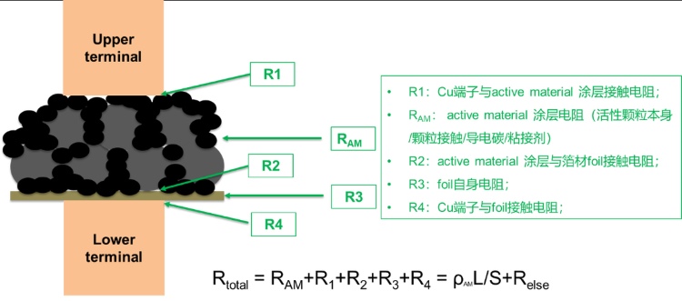
Figure 1. Schematic diagram of the two-probe method for measuring the resistance of the pole piece
1.Experimental Equipment and Test Methods
1.1 Experimental Equipment
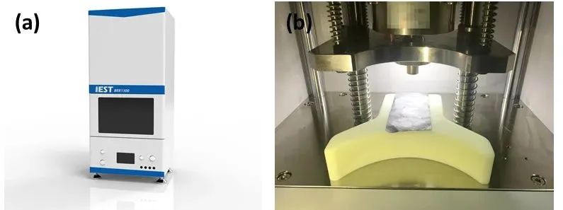
The test equipment model is BER2500 (IEST), the electrode diameter is 14mm, and the pressure range that can be applied is 5~60MPa.
The equipment is shown in Figure 2 (a) and (b)
Figure 2. (a) Appearance of BER2500; (b) Structure of BER2500
1.2 Sample Preparation and Test
Three states of ternary pole pieces were prepared: unrolled, low pressure rolled and high pressure rolled. The BER2500 pole sheet resistance meter is used for the resistance test under the condition of fixed pressure (25MPa). The adjustment of different thicknesses of the pole pieces is realized by controlling the gap of the coating blade, and the gap sizes are 125 μm, 150 μm, 200 μm, 250 μm, and 300 μm. Then these pole pieces were subjected to non-rolling, small-pressure rolling and high-pressure rolling respectively, and three kinds of pole pieces were obtained under each coating gap.
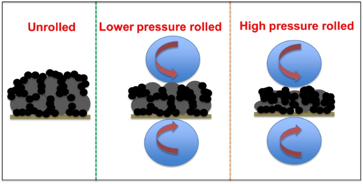
Figure 3. Three pole piece states
2. Data Analysis
The resistance obtained by the battery pole piece test includes the resistance of the coating itself and the contact resistance. Since the electrode formula and manufacturing process are the same, under the same compaction conditions, assuming that the resistivity ρ of the coating is the same, and the area S of the electrode test sample is also the same (a circle with a diameter of 14mm), then the thickness L of the electrode coating The relationship with the resistor RAM is: RAM = ρL/S. It can be seen from the formula that the greater the electrode thickness, the greater the electrode coating resistance. The resistivity of the electrode coating is related to the electrode formulation (the same for all samples in this paper) and the compaction density (different compaction density under different pressures). The contact resistance Relse includes the contact resistance of the probe on the coating side and the contact resistance of the interface between the coating and the current collector. The resistance R3 of the current collector itself and the resistance R4 of the probe on the current collector side are very small. It is 0.5mΩ when directly tested with an empty aluminum foil negligible compared to coatings. Among them, the contact resistance of the plane probe on the coating side is related to the state of the coating surface roughness generally. The smoother the coating surface, the lower the probe contact resistance. The contact resistance of the current collector and the coating is related to the compaction of the electrode. The greater the compaction, the larger the contact area between the coating and the current collector, the closer the contact, and the smaller the resistance. The total resistance of the tested electrodes is:
RAM = ρL/S + Relse
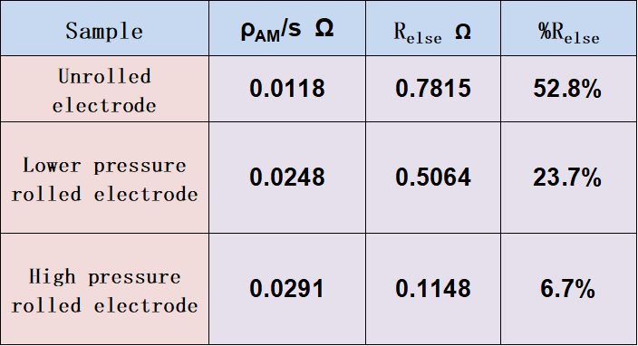
The resistance test was carried out on pole pieces with different thicknesses under three compaction states, and the relationship curve between the total resistance of the electrode test and the thickness of the electrode is shown in Figure 4. From the fitting results of the 5 points, the total resistance and the thickness basically satisfy a linear relationship, and the greater the rolling pressure, the higher the linearity. The slope and intercept results of the linear fitting are listed in Table 1. It can be seen from the formula that the slope of the straight line is the ratio of the resistivity of the coating to the area ρ/S, the area can be calculated if ρ is known, and the intercept is the contact resistance Relse. It can be seen from Figure 4 and Table 1 that for the non-rolled pole piece, the coating resistivity is relatively small, but as the rolling pressure increases, the coating resistivity becomes larger and larger. In the positive electrode sheet, the conductivity of the active particles is much lower than that of the conductive agent, and electrons are mainly transported through the conductive agent. The relatively high content of conductive agent in the non-rolled pole piece has formed a complete three-dimensional conductive permeable network, and the resistivity is relatively small. After rolling, the active particles are constantly compacted and in contact with each other, but this conductive network is cut off, and the electrode resistivity continues to increase.
Electrode coating resistance is related to electrode formulation, especially the content of conductive agent and coating compaction density. When the non-rolled pole piece may not have formed a conductive permeable network, proper rolling can increase the connectivity between conductive agents. lower the resistance. Therefore, the electrode coating needs to optimize the compaction according to the electrode formulation and microstructural characteristics. From the data, when the pole piece is not rolled, the ratio of the two contact resistances to the total resistance is relatively large, reaching 52.8%, which is mainly due to the weak adhesion between the coating and the current collector in the non-rolled pole piece. Strong, the interface contact resistance is relatively large. As the rolling pressure increases, the adhesion between the coating and the current collector gradually increases, the contact area increases and the resistance decreases; in addition, the surface of the coating is smoother after rolling, and the contact resistance of the probe on the coating side is also smaller. The proportion of the two kinds of contact resistance is only 6.7%, which shows that for the electrode sheet with high pressure rolling (compaction density about 3.5g/cm³), the electronic conductivity of the active material layer is evaluated by the two-probe method. Less affected.
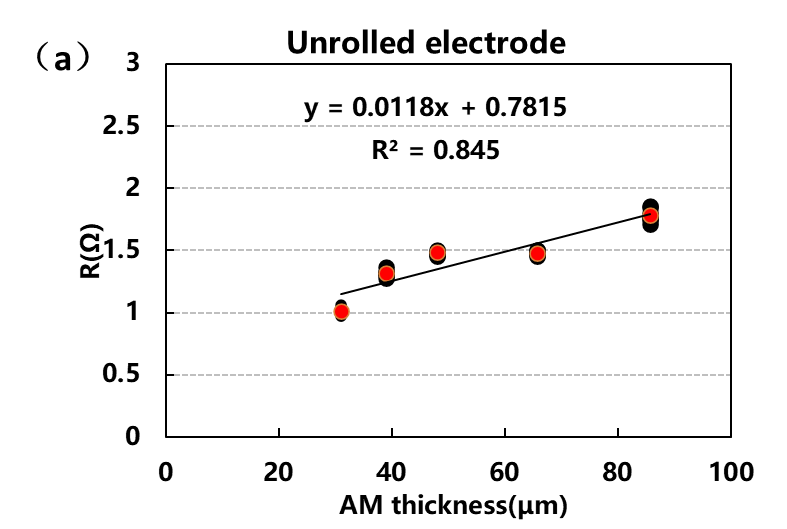
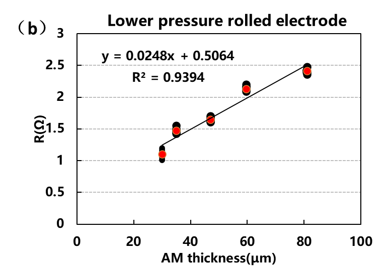
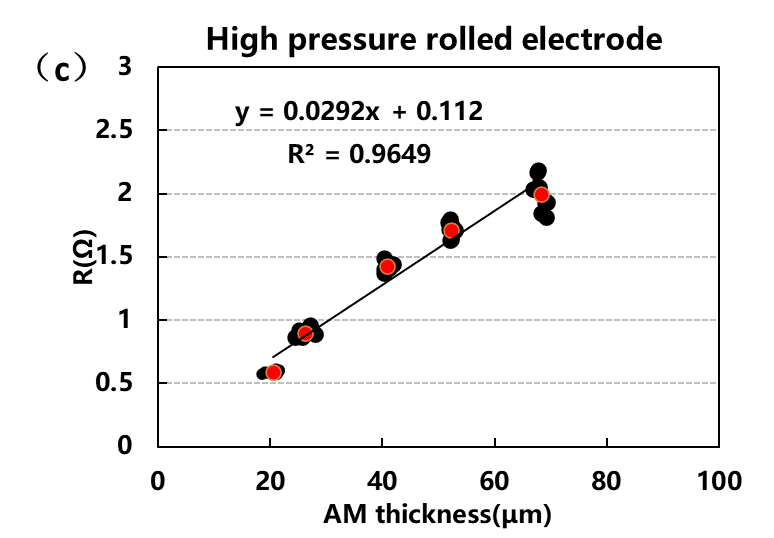
Figure 4. Resistance test curves of electrodes in three states
Table 1. Contact Resistance Statistics
3. Summarize
In this paper, by testing the resistance of positive electrode sheets with different thicknesses, combined with Ohm's law, the contact resistance in the electrode sheet is decomposed, and it is found that when the compaction of the electrode sheet is high, the contact resistance between the active material layer and the current collector and the contact resistance between the test terminal and the electrode The contact resistance of the sheet surface is relatively small, so the electronic conductivity of the active material layer can be evaluated more objectively.

