Effect of Pressure on Impedance of Li-ion Batteries
In recent years, lithium-ion batteries have been widely used in consumer electronics, electric vehicles, energy storage power stations and other fields due to their high specific capacity and safety. As people's demand for battery capacity is getting higher and higher, lithium battery companies, especially power battery manufacturers, are using more battery modules in parallel to meet the capacity needs of users. When packaging cells into modules, not only the strength and deformation of the module must be considered, but also the impact of packaging pressure on battery performance and safety¹, so it is very important to study the performance of lithium-ion batteries under different pressures.
Electrochemical Impedance Spectroscopy (EIS), as a non-destructive electrochemical analysis and detection method, can be used to reveal the internal dynamics of lithium-ion batteries, including the transport of electrons and ions, charge transfer reactions, and solid-state diffusion. Thus, it is a powerful tool for lithium-ion battery safety diagnostics²⁻³. In this paper, combined with the in-situ swelling analyzer (SWE2110,IEST) and the Princeton Electrochemical Workstation, the impedance changes of cells with different SOCs under different pressures are studied, which is conducive to exploring the impact of pressure on batteries with different states of charge, and the impact on batteries. Thus, it has noticeable guiding significance for use of the cells and the packaging of the module.
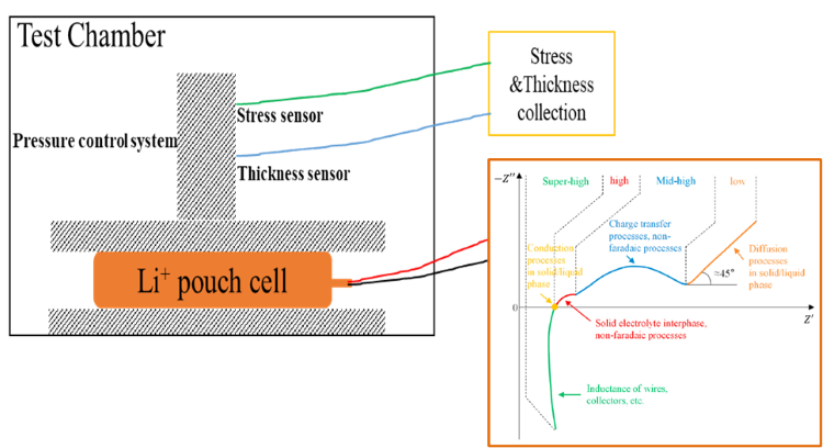
1.Experimental Equipment and Test Methods
1.1 Experiment Equipment
Figure 1(a) is the in-situ swelling analyzer, model SWE2110 (IEST); Figure 1(b) is the Princeton PARSTAT MC multi-channel multifunctional electrochemical workstation.
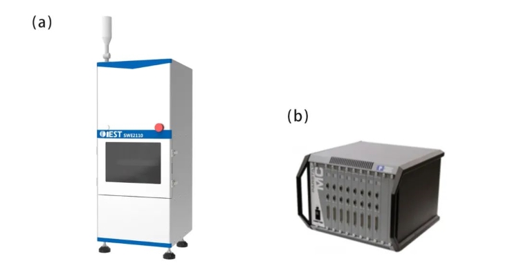
Figure 1. (a) Appearance of SWE2110 equipment; (b) Princeton Electrochemical Workstation
1.2 Test Information and Process
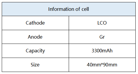
1.2.1 The cell information is shown in Table 1
Table 1. Information of Test Cell
1.2.2 Test Process
Adjustment of different SOCs: Charge 5 cells with constant current (CC) at a rate of 1C to 4.45V, and then charge with constant voltage (CV) until the current drops to 0.05C. Then discharge (DC) with a constant current at a rate of 0.2C for different times to obtain 5 cells with different SOCs, the SOCs of which are 0%, 20%, 40%, 60% and 80%, respectively.
Adjustment of different pressures: Take the 0% SOC cell as an example, put the cell into the inner cavity of SWE2110, open the MISS software, and set different pressure points and pressure holding time, where the applied force is 100kg, 200kg, 400kg, 600kg, 800kg and 1000kg (as shown in Figure 2(a)), the corresponding pressures are 0.27MPa, 0.54MPa, 1.1MPa, 1.6MPa, 2.2MPa and 2.7MPa, respectively. The adjustment and maintenance of pressures for other SOC cells are performed in the same steps.
EIS test: After holding the pressure for 20 minutes at each pressure, start the Princeton electrochemical workstation for the EIS test, and the frequency range is 10000Hz~0.02Hz, and the amplitude of the excitation voltage is 5mv.
2.Result Analysis
2.1 Nyquist Diagram Analysis of EIS at Different Pressures
EIS tests of different pressures were performed on cells with different SOCs, and the pressure gradient is shown in Figure 2(a). Under each test pressure, keep the pressure for 20 minutes to make all parts of the cell evenly stressed before starting the EIS test (one can observe whether the open circuit voltage remains stable for a long time). Taking the 0% SOC cell as an example (as shown in Figure 2(b)), the Nyquist diagram shows two semicircles. The semicircle in the high frequency region generally comes from the SEI film, while the semicircle in the middle and low frequency regions comes from the charge transfer. process³. As the pressure increases, the change in the high-frequency region is not obvious, but it can be seen from the inset of Figure 2(b) that the EIS in the low-frequency region (<0.125Hz) has a significant right-shift phenomenon, indicating that the charge transfer impedance and the diffusion resistance is more sensitive to pressure, and with the increase of pressure, the charge transfer process and diffusion process are less likely to occur. In addition, it can be seen from Figure 2(c)-(f) that as the SOC increases from 0% to 80%, the trend of low-frequency EIS moving to the direction of high resistance becomes weaker, indicating that the higher the SOC, the impedance of the low frequency region of the cell is less susceptible to pressure.
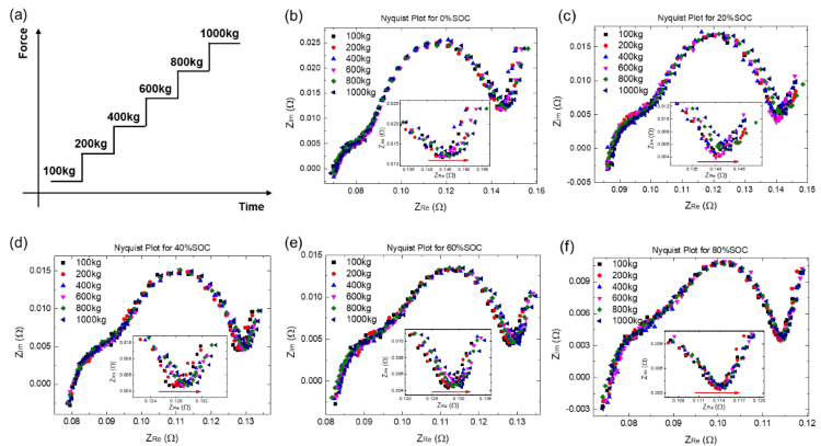
Figure 2.(a) Schematic diagram of stepped pressurization; (b-f) The EIS spectra of cells with 0%, 20%, 40%, 60% and 80% SOC respectively under different pressures (100kg, 200kg, 400kg, 600kg and 1000kg)
2.2 Bode Diagram Analysis of EIS at Different Pressures
Further, we selected three different SOCs of high (80%), medium (40%), and low (0%), and analyzed the Bode plots of these three cells under different pressures, as shown in Figure 3. It can be seen that the imaginary part of the EIS of these three SOC cells has no significant change under all pressures, no matter in the high-frequency region or the low-frequency region (as shown in Figure 3(b), (d), (f) ), However, different pressures mainly have obvious effects on the real part of the EIS in the low frequency region (as shown in Fig. 3(a), (c), (e)). In addition, it can also be seen from the insets of Figure 3(a), (c), and (e) that as the SOC increases, the increasing trend of the real part of the low-frequency region becomes less obvious, which is consistent with the previous results analyzed from the Nyquist diagram, indicating that the higher the SOC, the less susceptible the real part of the low-frequency EIS to the pressure.
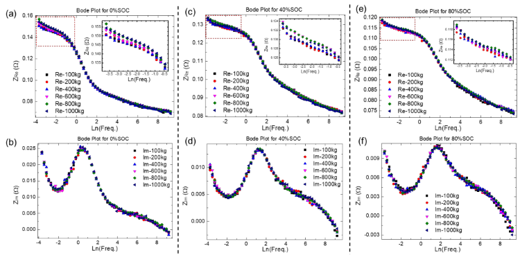
Figure 3. (a-b) are the real and imaginary parts of the 0% SOC cell as a function of frequency; (c-d) are the real and imaginary parts of the 40% SOC cell as a function of frequency; (e-f) are the real part and imaginary part of the 80% SOC cell as function of frequency.
2.3 Equivalent Circuit Analysis
Figure 4(a) is the Randles equivalent circuit commonly used in lithium-ion batteries. When a current flows, the total current at the working interface includes two parts: ic is used for charging the double electric layer and if is used for the Faraday reaction. The Faraday impedance can be divided into charge transfer impedance Rct and diffusion impedance (Warburg impedance) Zw. At higher frequencies, the Warburg impedance becomes less important relative to the Rct, so the Randles equivalent circuit can be simplified to the circuit diagram shown in Figure 4(b)⁴. The imaginary part of the impedance at high frequencies only comes from Cd, and from Figure 3(b), (d), and (f), it can be seen that the imaginary part does not change with the pressure, so the interface of the lithium-ion battery The electric double-layer capacitor remains stable under high pressure. When applying the pressure,the positive and negative electrodes of the lithium-ion battery, the separator and other components are compressed, and the contact interface between them is closer, which can effectively reduce the contact resistance. These interfacial contact resistances are included in the high-frequency resistance (ohmic impedance RΩ) reading from the real-axis intercept in the EIS spectrum. Usually, applying a small compressive load will improve the contact between different components in battery, whereas in this experiment the pressure was high and good contact was achieved at the component interface under all external pressures. Therefore, with a further increase in pressure, the ohmic resistance RΩ hardly changes so much.
However, it can be seen from the previous discussion that the real part of the EIS in low-frequency region increases continuously with the increase of pressure, and this phenomenon is more significant at low SOC. In order to quantitatively study-this phenomenon, we extracted the Rct of different SOC cells under different pressures, and the results are shown in Figure 4(c). It can be seen that when the pressure increases from 100kg to 1000kg, the Rct of the 0% SOC cell increases ~3.78 mΩ, however, the Rct of the 80% SOC cell only increases~1.34 mΩ, and the higher the SOC, smaller increase of the Rct with increasing the pressure. On the one hand, the external pressure will cause the positive and negative coatings to be compressed and deformed, the porosity of the active coating will decrease, the ion transport resistance will increase, and even the particles will be compressed and broken, which will eventually lead to an increase in Rct. On the other hand, when the cell is at 0% SOC, there is almost no intercalation of lithium between the layers of the graphite negative electrode, so it is easier to be compressed. When a certain pressure is applied, the interlayer spacing of the graphite layer is gradually reduced during the compression process, and the van der Waals force between the layers increases¹. At this time, the charge transfer process of Li⁺ and the subsequent diffusion and intercalation process will be greatly affected. making the diffusion impedance in the low frequency region increase significantly. When the cell is at 80% SOC, the graphite negative electrode is close to the state of fully intercalated lithium. At this time, the graphite layer can withstand greater pressure without being significantly compressed. Therefore, although the 1000kg of pressure is also applied, to the cell with 80% SOC, the increase of the van der Waals force of the graphite negative electrode is not as obvious as that of the cell with low SOC cell. Thus, the charge transfer of Li⁺ and its subsequent diffusion and embedding process are less resisted than those of low-SOC cells, so the Rct of cell with 80% SOC only increases about ~1.34 mΩ under high pressure, which is only 35% of the increasement of that at 0% SOC. Therefore, when it is necessary to apply a certain preload to the cell (for example, when packaging a module), we can predict that if the initial SOC of the cell is high, the preload will not have a significant impact on the cycling performance of the cell. However, when the initial SOC of the cell is relatively lower, the excessive preload may reduce the lithium-interactable capacity of the graphite negative electrode, and affect the cycle efficiency of the cell.

Figure 4. (a) is the Randles equivalent circuit commonly used in lithium-ion batteries, and the shunt situation when the current passes through the working interface; (b) is the simplified equivalent circuit after ignoring the Warburg impedance when the frequency is high; (c) is the change of charge transfer resistance Rct of different SOC cells with different pressures
3.Summarize
In this paper, the in-situ swelling analyzer (SWE2110) was used in combination with the Princeton PARSTAT MC multi-channel multifunctional electrochemical workstation to test and analyze the EIS of LCO/Gr system cells with different SOCs under different pressures, it ts found that the imaginary part of EIS is not affected by the pressure, that is, the interfacial electric double-layer capacitor of the lithium-ion battery can remain stable under high pressure. For the real part of the EIS with, different pressures, although the real part of the EIS in high-frequency region does not change significantly, but the pressure has a greater impact on the real part of the EIS in low-frequency region, and the lower the SOC, the Rct and the real part of low-frequency EIS shift toward to the larger resistance value. On the one hand, external pressure will deform the positive and negative coatings-increase the ion transport resistance, and even break the particles, which will eventually lead to a synchronous increase of the Rct; On the other hand, high pressure will squeeze the graphite electrode, increasing the van der Waals force betweenthe graphene layers, resulting in greater resistance to the charge transfer process of Li⁺ and the subsequent diffusion and intercalation process. Moreover, as the delithiation degree of the graphite increases (that is, the smaller the SOC), the easier the graphene-layer is compressed, and the greater the resistance becomes. Therefore, when we need to apply a large pre-tightening force to the cell, try to apply the pressure when it is in the high SOC state, so that to minimize the impact of pressure on the cycle efficiency of the cell.
4.References
[1] H.M. Lu, H.F. Fang, X.M. He and L.Q. Xie, Effect of pressure on charge and discharge performance and expansion of ternary lithium battery. J. Power Technol. 41 (2017) 686-688.
[2] W.X. Hu, Y.F. Peng, Y.M. Wei, Y. Yang, Application of Electrochemical Impedance Spectroscopy to Degradation and Aging Research of Lithium-Ion Batteries. J. Phys. Chem. C 127 (2023) 4465-4495.
[3] Q.C. Zhuang, Z. Yang, L. Zhang and Y.H. Cui, Research process on diagnosis of electrochemical impedance spectroscopy in lithium-ion batteries. Prog. Chem. 32 (2020) 761-791.
[4] Allen J Budd, Larry R Faulkner, Electrochemical Methods-Principles and Applications [M], Second Edition, Chemical Industry Press, 2005.
