Characterization and Applications of Tortuosity & MacMarlin Number
The Correlation between Electrode Porosity and Electrochemical Performance of Batteries
In lithium-ion batteries, as the thickness of the positive or negative electrode of the battery increases, the proportion of active materials also increases significantly, which can effectively increase the energy density of the single battery. Therefore, the development of thick electrodes is of great significance to improve the energy density of the battery. However, as the thickness of the electrode increases, the liquid phase lithium-ion transport of the electrode piece is blocked, resulting in an increase in the internal resistance of the battery, a decrease in the utilization of active materials, and a significant attenuation of cycle performance and rate performance [1].
Scientific researchers usually test rate performance and cycle performance by assembling button batteries or pouch batteries. However, long-cycle testing of batteries will lead to low R&D efficiency, so shortening the material evaluation cycle becomes particularly important. The tortuosity of the pole piece represents the degree of curvature of the porous electrode transmission path. It is another important parameter related to transmission characteristics in addition to porosity[2]. It can characterize the ease of migration of lithium ions in the coating, thereby reflecting the performance of the battery. rate performance. By analyzing the correlation between the tortuosity of the pole piece and the rate performance of the battery, this article can preliminarily judge the rate performance of the battery at the pole piece end and improve the research and development efficiency of materials or pole pieces.
1.Test Conditions & Methods
1.1 Test Equipment
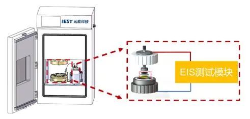
Assembly and testing of symmetrical batteries: The multi-channel ion conductivity test system (MIC1400) developed by IEST is used as shown in Figure 1. This equipment includes a four-channel symmetrical battery assembly jig, electrochemical impedance test system, fitting software, etc. It can provide high-purity argon atmosphere to realize multi-channel rapid electrochemical impedance spectroscopy testing. Frequency range 1000~0.1HZ.
Half-cell Assembly and Testing: Use steel shell 2032 to assemble a half-cell with pole pieces and lithium pieces and test its electrochemical performance through charging and discharging equipment.
Figure 1. Schematic diagram of the multi-channel ion conductivity testing system
1.2 Test Sample
Preparation of negative electrode sheets of different thicknesses: Select graphite as the active material to prepare the slurry and prepare the electrode sheets of different thicknesses by controlling the gap of the coating blade. The gap sizes are 100 μm, 200 μm, and 400 μm respectively.
1.3 Testing Process
Tortuosity test: stack the pole piece and diaphragm in the order of pole piece - diaphragm - pole piece and put them into 4 channels——>Close the door, evacuate the inner cavity and fill it with high-purity argon gas to remove the moisture in the inner cavity -> Inject quantitative liquid into each channel, and then test the EIS of the battery after 10 minutes of standing ->Finally, through software fitting and calculation, the tortuosity of the pole piece is obtained.
Battery Test: Test the charge and discharge performance of the battery at different rates (0.1C/0.2C/0.5C) respectively.
1.4 McMullin Number Calculation Method

In the formula: τ is the tortuosity; Rion is the ionic resistance; A is the pole piece area; ε is the pole piece porosity; σ is the electrolyte conductivity; d is the pole piece thickness.Since the testing method of pole piece porosity is relatively complicated, the ratio of tortuosity and porosity, that is, McMullin number (Nm=τ / ε), is usually used to characterize the tortuosity of the pole piece, as shown in Equation (2).

The electrochemical workstation was used to test the impedance of the symmetrical cell, and the obtained EIS is shown in Figure 2. Currently, the Nyquist diagram of the electrochemical impedance spectrum has the shape of the intersection of the low-frequency region line segment and the high-frequency region line segment. This is a typical Nyquist diagram without electrochemical reaction. Extend the low-frequency line segment in the Nyquist diagram until it intersects the X-axis.
Three times the difference between the intersection point and the intersection point of the high-frequency line segment and the X-axis is the ionic impedance Rion of the pole piece coating. Substituting the fitted ion impedance Rion into formula (2) to calculate the McMullin number of the pole piece, and then analyze the tortuosity of the pole piece.
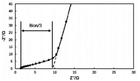
Figure 2. Electrochemical impedance spectrum of symmetrical battery
2. Results Analysis
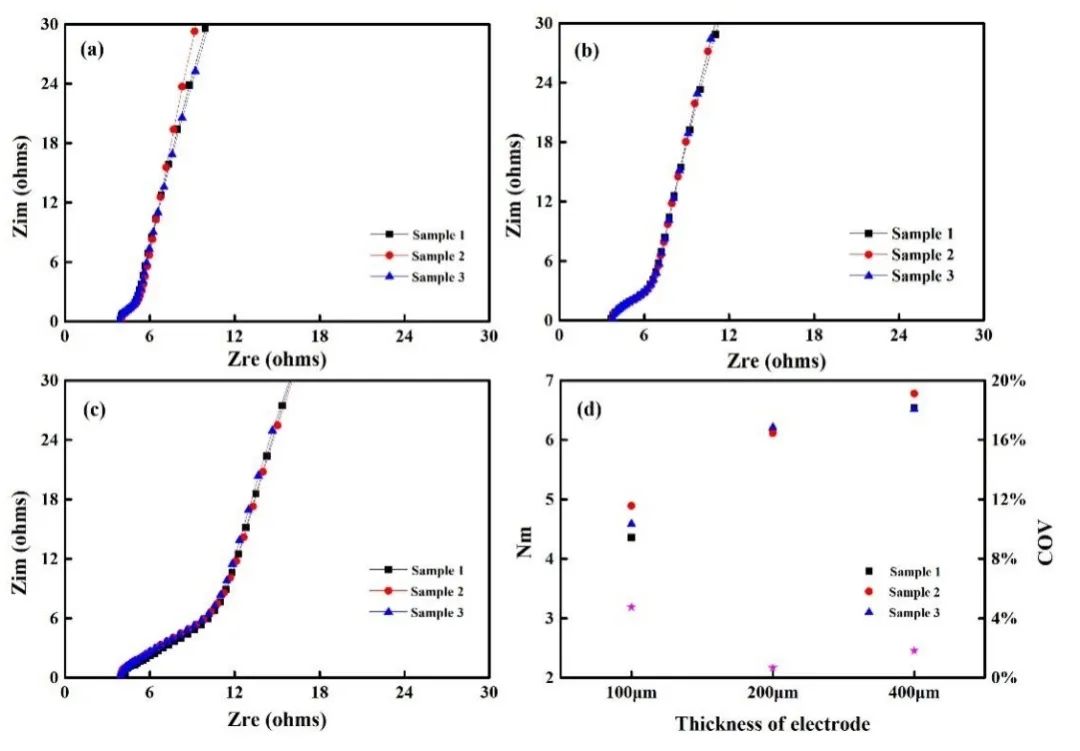
Figure 3. Impedance spectra of negative electrode plates with different thicknesses: 100 μm (a); 200 μm (b); 400 μm (c) and the corresponding McMullin number (d)
Electrochemical impedance spectroscopy tests were performed on symmetrical batteries assembled with negative electrode sheets of different thicknesses. The results are shown in Figures 3(a), 3(b), and 3(c). Fit the impedance spectrum to obtain the ion resistance of each pole piece, and then substitute the ion resistance value into formula (2) to obtain the pole piece McMullin number, as shown in Figure 3(d). The corresponding McMullin numbers of 100 μm, 200 μm, and 400 μm are 4.61, 6.15, and 6.61 respectively. From the trend of the data, the McMullin number increases with the increase of the pole piece thickness.
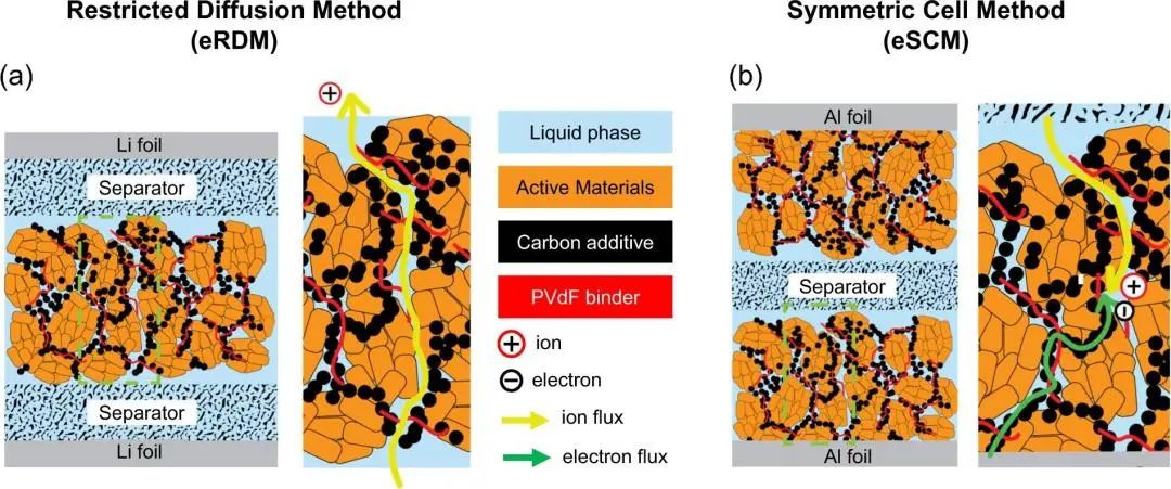
Due to the complex connections between the pores in the porous electrode, such as blind holes, semi-through holes, small throat sizes, etc., when the thickness of the pole piece increases, the ion transmission path tends to be more tortuous, and the actual transmission distance increases exponentially, resulting in a higher tortuousness of the pore. Generally, for porous electrodes, electrochemical methods for testing pore tortuosity include: (1) Polarization-Interrupt Method (eRDM), in which a fixed direct current "interrupts" the current after polarizing the battery for several minutes, during the polarization process, Li+ ions are generated at one electrode and consumed by deposition at the other electrode, creating a concentration gradient in the battery.
After the current is discontinued, this concentration gradient is then allowed to relax or equilibrate. As the battery relaxes, the electrical potential gradually approaches zero. Plot a semi-logarithmic plot of cell potential versus time and use the slope of the relaxation curve to calculate the MacMullin number and tortuosity value (Figure 4a); (2) Electrochemical impedance method (eSCM), measuring the electrode impedance in non-embedded symmetrical cells, and fitting the resulting impedance curve on the Nyquist diagram, thus, the effective ionic resistance (Rion) of the electrode was determined, and the MacMullin number and curvature of the electrode were calculated (Figure 4b), which is the method used in this article.
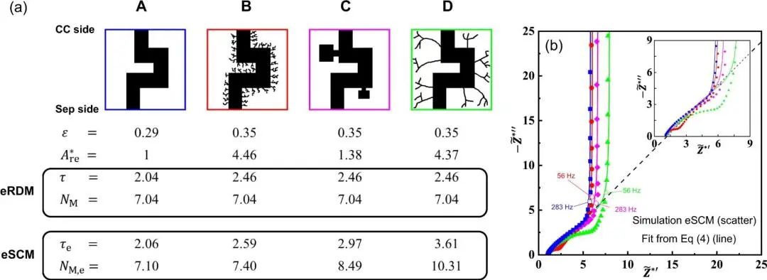
Using these two methods, assuming the four conditions of electrode porosity as shown in Figure 5, when using the first eRDM method to simulate the test, the MacMullin numbers are exactly the same, in fact, due to the complexity of the pore structure, when using the second eSCM method for simulation testing, the results show that even when the porosity is the same, the pore tortuosity and MacMullin number are completely different due to different pore structures. The testing equipment we developed is more in line with actual conditions and can reflect the performance of the electrode.
Figure 4. Schematic diagram of the electrochemical testing method for pore tortuosity [3]
Figure 5. Comparison of results of two testing methods for pore tortuosity [3]
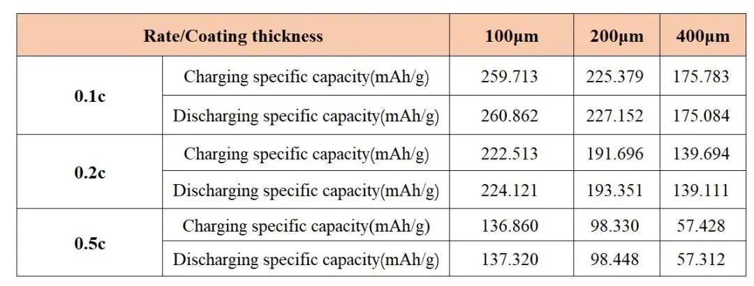
Figure 6 and Table 1 show the capacity and capacity retention rates of negative electrode sheets of different thicknesses at different rates. It can be seen from this that the capacity of each pole piece decreases as the magnification rate increases, but the capacity retention rate is 100 μm>200μm>400μm, this shows that the pole piece coated with 100 μm has the best rate performance, and the 400 μm pole piece has the worst performance. Combining the data of McMullin number, as the thickness of the pole piece increases, the tortuosity of the pole piece becomes larger, and the rate performance of the battery deteriorates.

Figure 6. Electrochemical properties of pole pieces at different rates: capacity-voltage curve (a); rate-capacity retention curve (b)
Table 1. Specific Capacity of Pole piece at Different Magnification Rates
The electrochemical performance test results and the pore tortuosity test results can be completely matched. This shows that through the test of electrode pore tortuosity, we can predict the performance of the electrode, quickly correlate the electrode structure and performance prediction, and accelerate the design and process development of the electrode.
Summarize
In this article, symmetrical cells and half-cells were assembled using graphite negative electrode sheets of different thicknesses, and the tortuosity of the electrode sheets and the rate performance of the battery were tested, it was found that the tortuosity of the electrode piece increases with the increase of thickness, and the rate performance of the battery decreases with the increase of thickness, indicating that there is a certain correlation between the tortuosity of the electrode piece and the rate performance of the battery.
Therefore, we can initially judge the rate performance of the battery by testing the tortuosity of the pole pieces. In addition to judging the rate performance of pole pieces with different thicknesses, the test of pole piece tortuosity can also be used to study the effects of electrode formula, porosity, main material morphology, electrolyte type, separator type, etc. on the performance of lithium-ion batteries.
References
[1] Sun Weibing et al. A thick electrode with low tortuosity and its preparation method and application. CN115312777A. 2022.
[2] Wang Chenyang, Zhang Anbang, Chang Zenghua, et al. Progress in the design and preparation technology of porous electrode structures for lithium-ion batteries [J]. Materials Engineering, 2022, 50 (1): 67-79.
[3] Benjamin Delattre, Ruhul Amin, Jonathan Sander, Joël De Coninck, Antoni P. Tomsia1 and Yet-Ming Chiang. The electrode tortuosity factor: why the conventional tortuosity factor is not well suited for quantifying transport in porous Li-ion battery electrodes and what to use instead [J]. Electrochem. Soc. 2018,165:A388.

