Comparison of the Swelling Behavior of Three Common Cathode Systems in Battery Cells
As the most common energy carrier at present, lithium battery has been widely used in all aspects of life. When the battery is in use, chemical and electrochemical reactions are happening inside it all the time, causing the shape of the lithium battery to change to a certain extent with these reactions. The swelling of the battery is usually divided into two types: one is the hard swelling caused by the structure change of the positive and negative electrode materials deintercalating lithium; the other is the soft swelling caused by the gas production reaction inside the lithium battery. Hard swelling has always been accompanied by the cycle charge and discharge process of lithium batteries, and there will be some irreversible swelling as the number of cycles increases.
In the current lithium battery system, graphite is the most commonly used negative electrode, while lithium cobalt oxide LCO, ternary NCM, and lithium iron phosphate LFP are the most common positive electrodes. Different positive and negative electrode materials have different structural phase transitions during charging and discharging, therefore, different swelling behaviors will be shown at the cell end. Understanding the swelling differences of these different systems can help developers to choose the appropriate material system design according to actual application requirements. In this paper, an in-situ swelling test system is used to monitor the swelling force and swelling thickness curves of the three systems of cells during charging and discharging, and the swelling difference is analyzed in combination with electrical properties.
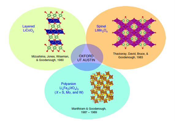
Figure 1. Comparison of Three Positive Electrode Structures
1.Test Equipment: SWE2110 in-situ swelling test system, the appearance is shown in the figure below.
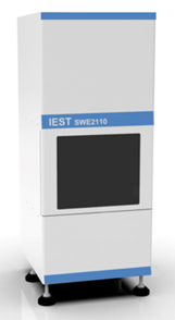
Figure 2. Appearance of SWE2110 Equipment
2. Testing Parameters
2.1 Battery Information is Shown in Table 1
Table 1. Battery Information
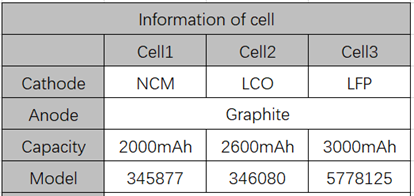
2.2 Test Process: Place the battery cell in the test chamber of the in-situ swelling analyzer (SWE2110), set the constant pressure test mode and the constant gap test mode respectively, adjust the initial pressure to 0.2MPa, turn on charging and discharging, and monitor the swelling curve of each cell system in-situ during charging and discharging.
Result Analysis
During the charging and discharging process of lithium battery, lithium-ion will shuttle back and forth between the negative electrode, electrolyte, positive electrode, the battery undergoes a certain degree of swelling and deformation, which is mainly the result of the combined effect of the positive and negative electrode material deintercalation lithium phase transition.
Generally, the volume change of the unit cell caused by the phase transition of the positive electrode material is smaller than that of the negative electrode material. For example, during the charging process, the volume shrinkage of the layered LiCoO2 unit cell (delithiation 0.5) is about 1.9%, the volume of the Li(Ni,Co,Mn)O2 unit cell changes by about 2%, the volume of the LiFePO4 unit cell with the olivine structure changes by about 7%, and the volume of the unit cell expands by about 10% after graphite intercalation, the swelling trend during charge and discharge is basically dominated by the negative electrode material.
Therefore, whether it is a cell of LCO/graphite system, NCM/graphite system, or LFP/graphite system, the swelling thickness change curve and swelling force change curve we measured all show charging swelling, the phenomenon of discharge shrinkage (as shown in Figure 3(a)). From the actual measured cell swelling thickness percentage, there is a difference between the actual cell swelling thickness and the theoretical cell swelling change, this is mainly because when calculating the swelling percentage at the cell end, the total swelling thickness is divided by the total thickness of the cell, and the denominator part is the sum of the positive and negative pole pieces, the molecular part is mainly the swelling of the negative electrode, thus resulting in a calculated percentage that is smaller than that of the individual graphite unit cell swelling.
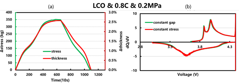
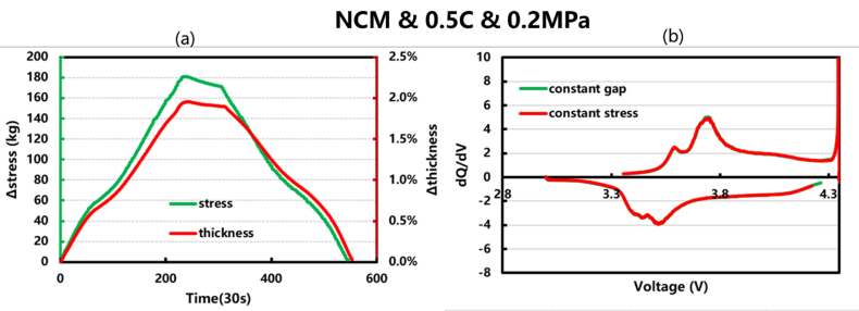
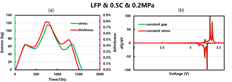
Figure 3. The swelling thickness and swelling force curves and differential capacity curves of the in-situ test of the cell(Green constant gap mode, red constant pressure mode)
Although the swelling curve trend of the conventional system cell is consistent with the charge and discharge process of the negative electrode material, the swelling behavior of the positive electrode material will also affect the trend of the entire process. For example, the swelling curve of the LFP system cell in Figure 3 will appear a "hump" phenomenon, this may be due to the olivine structure of LiFePO4, and the delithiation product of LiFePO4 during charging is iron phosphate (FePO4), the charging and discharging process is in the state of FePO4/LiFePO4 two-phase coexistence. The structure of FePO4 and LiFePO4 is similar. In terms of volume, the volume of FePO4 is 6.81% 2 smaller, in the early stage of battery charging, LiFePO4 does not shrink significantly, and graphite expands, so the pressure rises, and FePO4 shrinks in the middle of charging, which will offset part of the swelling of graphite, and the swelling force will drop, and LFP will no longer shrink in the later stage, but graphite continues to expand, so the swelling force increases again, and the discharge process is reversed.
In the NCM/graphite system in Figure 3, we can find that there is a tendency to slightly reduce the swelling thickness and swelling force during the charging constant voltage stage, which is mainly due to the fact that the transition metal in the positive electrode material is in a very high valence state at this time. , the Li content is very low, and the Li layer is in an unstable swelling state. When the material is further deliminated, the material structure collapses, resulting in a decrease in the c-axis, thereby reducing the cell swelling.
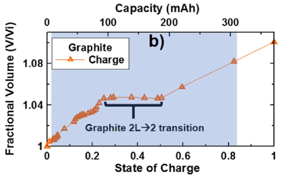
Figure 4. Swelling of Lithium Intercalation Structure of Graphite Crystal
Further analysis of the differential capacity of the three systems of batteries, as shown in Figure 3(b), shows that there are 2 to 3 obvious lithium deintercalation peaks during the charge and discharge process, this may mainly represent the LiCx phase transition of lithium intercalation and deintercalation of graphite, and the peak position and peak intensity are related to the polarization and reaction capacity of the cell.
From the comparison of the two different swelling measurement modes, the two different boundary conditions of constant pressure or constant gap are limited, in the short-term cycle process, the electrical performance is not greatly affected, but if the impact on the long-term cycle is taken into account, further experimental verification is needed.
Summarize
In this paper, the swelling force and swelling thickness curves of three different systems of batteries are characterized by using the in-situ swelling analysis system (SWE2110), combined with the phase transition of positive and negative electrode materials to deintercalate lithium to analyze the differences in the swelling curves. The LFP system battery will appear a "hump" phenomenon during the charge and discharge process, however the LCO and NCM systems do not have this phenomenon, and the NCM cells will show a tendency to slightly reduce the swelling during the constant voltage charging stage.
The comparison of these swelling phenomena can, on the one hand, provide a method for lithium battery researchers to characterize the swelling performance of the cell in-situ, and on the other hand, provide a data mechanism reference for the study of the swelling performance of the specific system cell.
